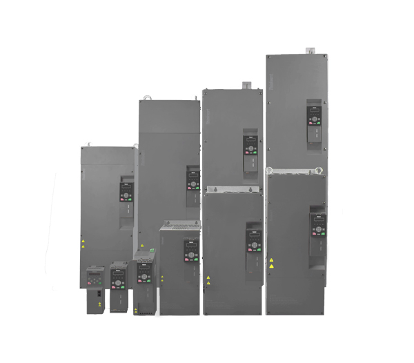
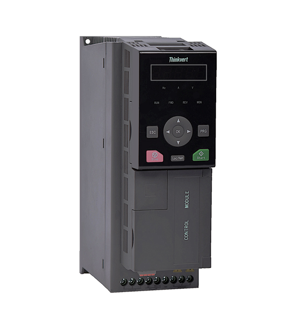
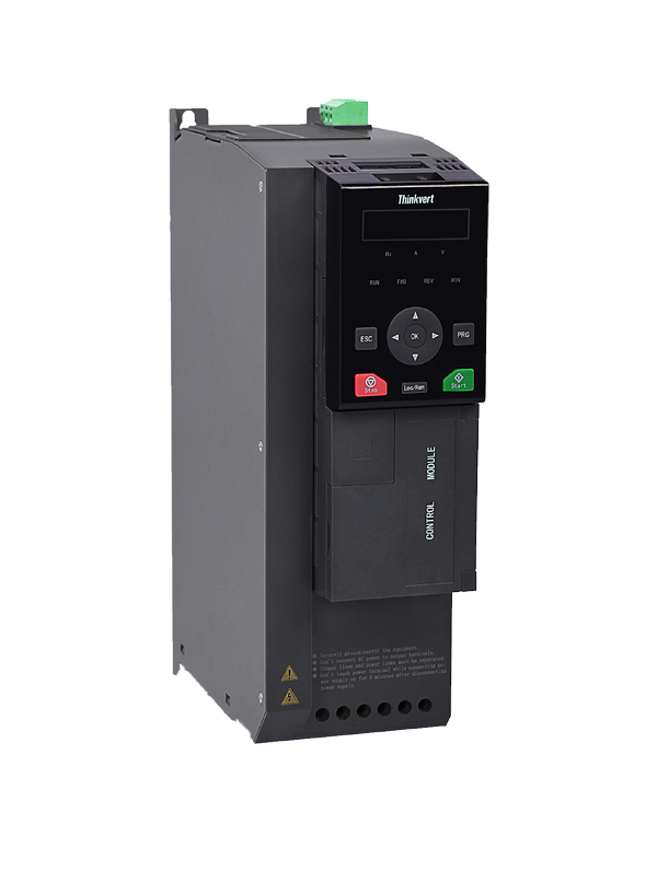
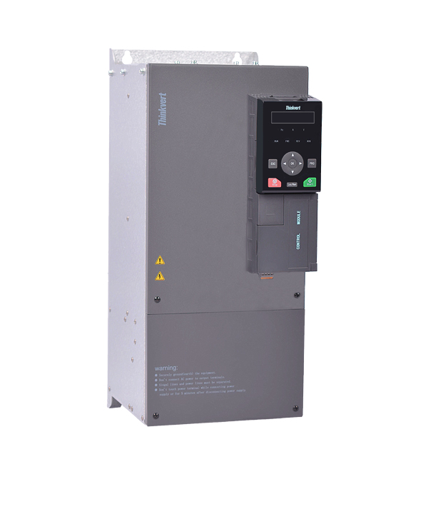
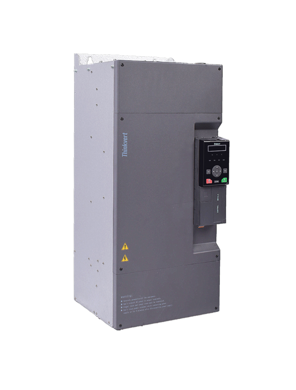
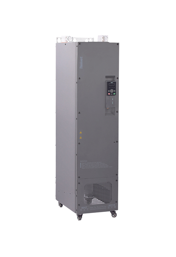
TI120 Series Variable Frequency Drive
1.1 Product Naming
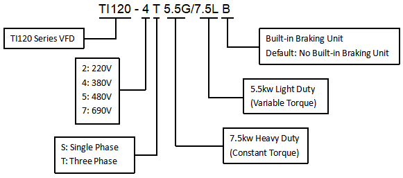
Figure 1-1 Product Naming
1.2 Description of Product Nameplate
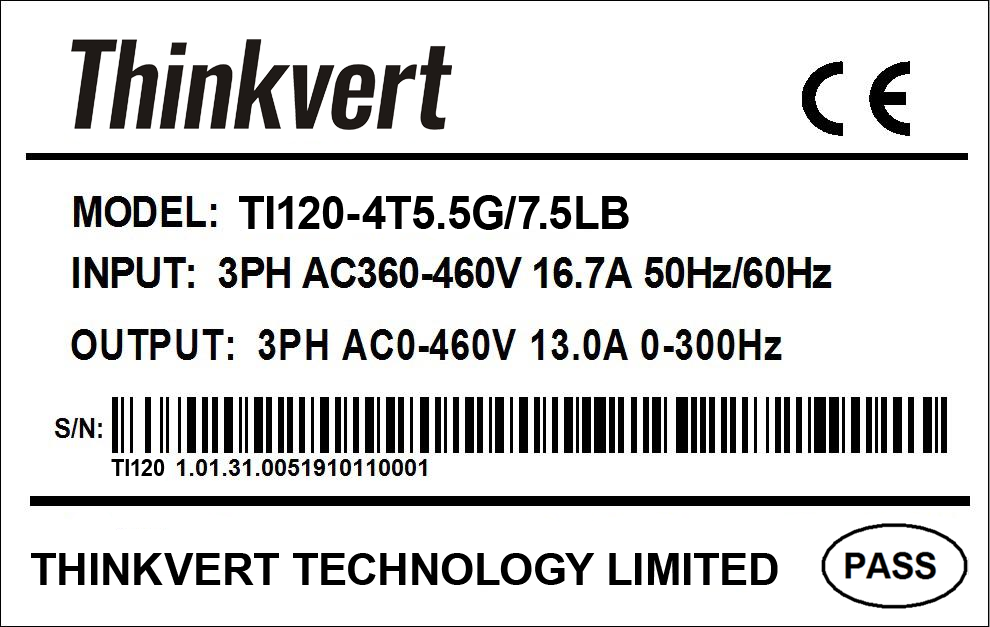
Figure 1-2 Description of Product Nameplate
2.1 Peripheral system connection diagram

Figure 2-1 Connected peripheral system configuration diagram
2.3.1 Standard wiring diagram
The standard wiring is as shown in the following figure:

Figure 2-4 Standard Wiring Diagram
Table 8-3 TI120 Installation Dimensions
| VFD model | Appearance and installation dimensions (mm) | ||||||
| W | H | D | W1 | W2 | H1 | Installation
Aperture |
|
| TI120-4T1.5G/2.2LB | 81 | 237 | 173 | 67.5 | 57 | 224.5 | 4.5 |
| TI120-4T2.2G/3.7LB | |||||||
| TI120-4T3.7G/5.5LB | |||||||
| TI120-4T5.5G/7.5LB | |||||||
| TI120-4T7.5G/11LB | 95 | 297 | 222 | 73.5 | 73.5 | 287.5 | 6 |
| TI120-4T11G/15LB | |||||||
| TI120-4T15G/18.5LB | |||||||
| TI120-4T18.5G/22LB | 185 | 440 | 245 | 140 | 140 | 427.5 | 7 |
| TI120-4T22G/30LB | |||||||
| TI120-4T30G/37LB | |||||||
| TI120-4T37G/45L | 265 | 604.5 | 269.5 | 180 | 148.5 | 580 | 9.5 |
| TI120-4T45G/55L | |||||||
| TI120-4T55G | 265 | 690 | 323 | 200 | 200 | 674 | 9.5 |
| TI120-4T75G/90L | |||||||
| TI120-4T90G/110L | 295 | 852 | 338.5 | 200 | 200 | 810 | 12 |
| TI120-4T110G/132L | |||||||
| TI120-4T132G/160L | |||||||
| TI120-4T160G/185L | 335 | 1070 | 418 | 265 | 265 | 1046.5 | 14 |
| TI120-4T185G/200L | |||||||
| TI120-4T200G/220L | |||||||
| TI120-4T220G/250L | 339 | 1113 | 546.5 | 265 | 175 | 1081.5 | 14 |
| TI120-4T250G/280L | |||||||
| TI120-4T280G/315L | |||||||
| TI120-4T315G/355L | 339 | 1300 | 546.5 | 265 | 175 | 1267.5 | 16 |
| TI120-4T355G/400L | |||||||
| TI120-4T400G/450L | |||||||
| TI120-4T450G/500L | |||||||
| TI120-4T500G/560L | 999 | 1300 | 500 | 750 | 750 | 1390 | 16 |
| TI120-4T560G/630L | |||||||
| TI120-4T630G/710L | |||||||
| TI120-4T710G/800L | |||||||
8.1 Technical Specifications and Installation Dimensions of TI120 Series Variable Frequency Drive
8.1.1 Technical specification
Table 8-1 TI120 Model and Specification of Series VFD
| Program | Specification | ||||||||||||||||||
| TI120-4TXXXG(B)
TI120-4TXXXL(B) |
1.5 | 2.2 | 3.7 | 5.5 | 7.5 | 11 | 15 | 18.5 | 22 | 30 | 37 | 45 | 55 | 75 | 90 | 110 | |||
| Adapted motor power (kW) | 1.5 | 2.2 | 3.7 | 5.5 | 7.5 | 11 | 15 | 18.5 | 22 | 30 | 37 | 45 | 55 | 75 | 90 | 110 | |||
| Input | Rated input current (A) | 4.6 | 6.3 | 11.4 | 16.7 | 21.9 | 32.2 | 41.3 | 49.5 | 59.0 | 57.0 | 69.0 | 89.0 | 106 | 139.0 | 164 | 196 | ||
| Output | Rated output current (A) | 3.8 | 5.1 | 9.0 | 13.0 | 17.0 | 24.0 | 32.0 | 37.0 | 45.0 | 60.0 | 75.0 | 90.0 | 110 | 150 | 180 | 210 | ||
| Output Voltage | 3-phase 0V~rated input voltage | ||||||||||||||||||
| Maximum output frequency | 300.00Hz (modified by parameters) | ||||||||||||||||||
| Carrier frequency | 1.0 khz~16.0 KHz (carrier frequency can be automatically adjusted according to load characteristics) | ||||||||||||||||||
| Overload capacity | 150% rated current 60s; 180% rated current 10s;; 200% rated current 0.5s | ||||||||||||||||||
| High frequency leakage
Current Countermeasure |
DC reactor | External option | |||||||||||||||||
| Brake
Function |
Brake unit | Standard built-in | Built-in optional | ||||||||||||||||
| Power supply | Fixed voltage Rated frequency | AC: three-phase 360 V~460 V
50Hz/60Hz |
|||||||||||||||||
| Allowable fluctuatio-n range of voltage | -15%~10%, actual allowable range: AC323V~528V | ||||||||||||||||||
| Allowable fluctuatio-n range of frequency | ±5% | ||||||||||||||||||
| Power supply capacity (kVA) | 5.0 | 6.7 | 12 | 17.5 | 22.8 | 33.4 | 42.8 | 45 | 54 | 52 | 63 | 81 | 97 | 127 | 150 | 179 | |||
| Program | Technical specification | ||||||||||||||||||
| TI120-4TXXXG(B)
TI120-4TXXXL(B) |
132 | 160 | 185 | 200 | 220 | 250 | 280 | 315 | 355 | 400 | 450 | 500 | 560 | 630 | 710 | ||||
| Adapted motor power (kW) | 132 | 160 | 185 | 200 | 220 | 250 | 280 | 315 | 355 | 400 | 450 | 500 | 560 | 630 | 710 | ||||
| Input | Rated input current (A) | 240 | 287 | 326 | 365 | 410 | 441 | 495 | 565 | 617 | 687 | 782 | 835 | 920 | 1050 | 1180 | |||
| Output | Rated output current (A) | 260 | 305 | 350 | 377 | 426 | 465 | 520 | 585 | 650 | 725 | 810 | 900 | 1090 | 1100 | 1300 | |||
| Output Voltage | 3-phase 0V~rated input voltage | ||||||||||||||||||
| Maximum output frequency | 300.00Hz (modified by parameters) | ||||||||||||||||||
| Carrier frequency | 1.0 khz~16.0 KHz (carrier frequency can be automatically adjusted according to load characteristics) | ||||||||||||||||||
| Overload capacity | 150% rated current 60s; 180% rated current 10s;; 200% rated current 0.5s | ||||||||||||||||||
| high frequenc-y leakage
Current Countermeasure |
DC reactor | Extern-al
Option
|
Built-in | External option | |||||||||||||||
| Brake
Function |
Brake unit | Built-in optional | External option | ||||||||||||||||
| Power supply | Fixed
voltage Rated frequency |
AC:3-phase 360V~460V
50Hz/60Hz |
|||||||||||||||||
| Allowable fluctuatio-n range of voltage | -15%~10%,Actual allowable range:AC 323V~528V | ||||||||||||||||||
| Allowable fluctuatio-n range of frequency | ±5% | ||||||||||||||||||
| Power
supply capacity (kVA) |
220 | 263 | 304 | 334 | 375 | 404 | 453 | 517 | 565 | 629 | 716 | 769 | 861 | 969 | 1092 | ||||
*1: the more rigorous selection method is that the rated output current of the variable frequency drive is greater than the rated current of the motor or the maximum load current.
Table 8-2 Technical Specification of TI120 Series Driver
| Program | Technical specification | ||
| Basic function | Input frequency resolution | Digital setting: 0.01Hz
Simulation setting: maximum speed ×0.025% |
|
| Control mode | Advanced scalar control
No PG vector control (SVC) PG vector control (VC) |
||
| Starting torque | SVC:0.25Hz 150%
VC: 0.00Hz 180% |
||
| Speed regulation range | SVC: 1:200 | VC: 1:1000 | |
| Speed stabilization precision | SVC: ±0.5% | VC: ±0.2% | |
| Torque control precision | SVC: above 5Hz±5% | VC: above 5Hz±3% | |
| Torque reentry precision | ≤0.5% rated torque of motor | ||
| Torque response time | SVC: ≤ 10ms (rated torque of motor) | VC: ≤ 5ms (rated torque of motor) | |
| Torque boost | Automatic torque lifting function; manual torque increases by 0.1%~30.0% | ||
| V/F curve | Straight line, multiple power curve, multiple point curve, V/F separation | ||
| Acceleration and deceleration curve | Straight line, broken line, S curve | ||
| Direct current brake | Starting frequency of DC brake :0.00~300.00Hz; DC braking current: constant torque 0.0~120.0%; variable torque 0. 0~90.0%
Direct current brake time: 0.0~30.0s;realize quick brake without direct current brake initial waiting time |
||
| Inching control | Inching frequency range:0.00Hz~50.00Hz
Inching acceleration and deceleration time range:0.0s~3600.0s |
||
| Process closed loop PID | The process closed loop control system can be conveniently realized | ||
| Simple PLC, multi-stage instruction | At most 16 speed stages can be easily realized through built-in simple PLC or X terminal. | ||
| Automatic voltage regulation | When the power grid voltage fluctuates, the output voltage can be automatically kept stable. | ||
| Overflow, over-voltage and stall control | The current and voltage during operation are automatically limited to prevent frequent over-current and over-voltage tripping. | ||
| Automatic fast current limiting | Minimize over-current faults and protect the normal operation of the drive. | ||
| Torque limit and control | “Excavator” feature automatically limits torque during operation to prevent frequent over-current tripping; in vector control, torque control can be realized. | ||
| Personal-ized
Function |
Not stop of instantaneous stop | In case of instantaneous power failure, the drive will continue to operate for a short period of time through the reduction of load feedback energy compensation voltage. | |
| Fast current limiting | Avoid frequent over-current fault of the drive. | ||
| Timing function | Realize timing control of the drive | ||
| Motor overheat protection | The motor temperature detection can be conveniently realized through an external sensor | ||
| Copy of parameters | Realize the uploading and downloading of parameters and the quick setting of parameters | ||
| Double-port Modbus | The double-port supports Modbus protocol and realizes simple networking function. | ||
| Power-on short circuit detection to ground | Power-on automatically completes short-circuit detection to ground | ||
| Magnetic flux
brake |
In cooperation with magnetic flux brake, faster deceleration and shutdown can be realized. | ||
| Run | Running instructions | Keyboard command, terminal command, communication command can be switched in a variety of ways | |
| Main speed command | 12 kinds of main speed command given way can be switched through a variety of ways | ||
| Auxiliary speed command | 9 kinds of auxiliary speed command given methods can flexibly realize auxiliary speed fine adjustment and speed synthesis. | ||
| Input terminal | l 7 X terminals, one of which supports high speed pulse input.
l 2 AI terminals, one supports 0~10V voltage signal and one supports 0~10V voltage signal or 0~20mA current signal |
||
| Output terminal | l 2 relay outputs
l 2 transistor outputs, one of which supports high speed pulse output. l 2 AO outputs, one supports 0~10V voltage signal and one supports 0~10V voltage signal or 0~20mA current signal |
||
| Human-c-omputer interaction | LED display | LED operation keyboard | |
| LCD display | LCD operation keyboard | ||
| Key locking function | Realize all key locking or partial key locking functions of the keyboard to prevent misoperation of the keyboard. | ||
| Keyboard emergency shutdown | Through the keyboard stop key, the machine can stop in any command source mode and reduce the operation risk. | ||
| Protectio-n function | Short circuit protection | Output interphase short circuit protection, output short circuit protection to ground. | |
| Over-current protection | Shutdown protection exceeding 2.2 times of the rated current of the drive | ||
| Over-voltage protection | Stop when the DC bus voltage of the main circuit is greater than 800V | ||
| Under-voltage protection | Stop when the DC bus voltage of the main circuit is less than 320V | ||
| Overload protection | At 150% rated current, stop the machine after 60 seconds of operation. | ||
| Overheat protection | Overheating protection of drive IGBT module | ||
| Phase-break protection | hree-phase input phase-break protection and three-phase output phase-break protection | ||
| Environ-ment | Use place | Indoor, not exposed to direct sunlight, no dust, corrosive gas, flammable gas, oil mist, water vapor, water droplets and salt, etc. | |
| Altitude | No derating is required below 1000m, derating is 1% for every 100m above 1000m, and the highest altitude is not more than 3000m. | ||
| Ambient temperature | -10 ~+40℃, derating between 40~50℃, derating 1.5% for every 1℃ increasing. | ||
| Humidity | 5-95%, no water condensation | ||
| Vibration | Less than 5.9 m/s2 | ||
| Storage
temperature |
-40~+70℃ | ||
| IP Grade | IP20 | ||
Contact form description text

