
Micro VFD

TI10 Series VFD
General Details
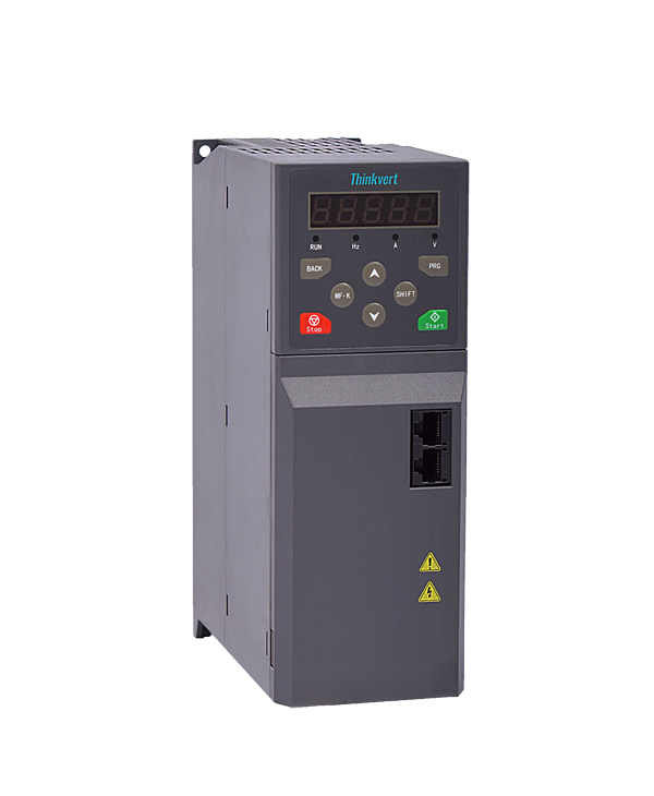
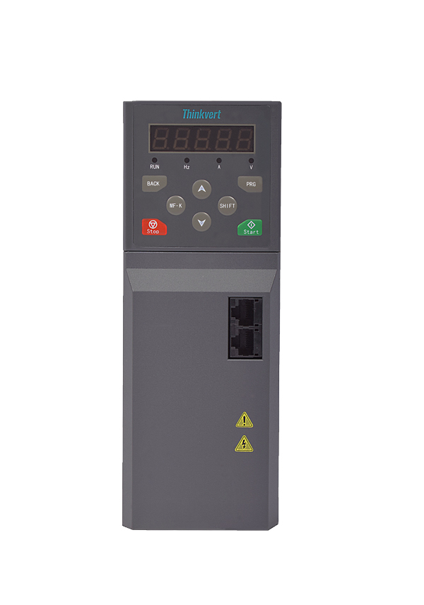
1.1 Appearance and installation dimensions

Figure1-1 Installation Dimension Diagram of TI10-4T0.75G/1.5LB~TI10-4T3.7G/5.5LB
Table1-1 TI10 Installation Dimensions
| Variable Frequency Drive model | Appearance and installation dimensions (mm) | ||||||
| W | H | D | W1 | W2 | H1 | Installation
Aperture |
|
| TI10-4T0.75G/1.5LB | 74 | 211 | 158 | 62 | 52 | 200 | 4.5 |
| TI10-4T1.5G/2.2LB | |||||||
| TI10-4T2.2G/3.7LB | |||||||
| TI10-4T3.7G/5.5LB | |||||||
1.2 Rated specifications
Table 1-2 rated specifications
| Variable Frequency Drive model | Power supply capacity(kVA) | input current (A) | Output current
(A) |
Adapted motor
(KW) |
| TI10-4T0.75G/1.5LB | 2.8 | 2.4 | 2.3 | 0.75 |
| TI10-4T1.5G/2.2LB | 5.0 | 4.6 | 3.8 | 1.5 |
| TI10-4T2.2G/3.7LB | 6.7 | 6.3 | 5.1 | 2.2 |
| TI10-4T3.7G/5.5LB | 12 | 11.4 | 9.0 | 3.7 |
1.5 Standard wiring diagram

Figure 1-2 Standard Wiring Diagram
1.5.1 Wiring description for control terminals

Figure 1-3 Layout of Control Terminal
Table 1-4 Function Description of Control Terminal
| Analog input | +10V | Analog input reference voltage | 10V ±1%,internally isolated from COM |
| The maximum output current is 20mA | |||
| GND | Analog ground | Internal isolation from COM | |
| AI1 | Analog input channel 1 | 0~10V:input impedance 22kΩ | |
| 0~20mA:input impedance 500Ω | |||
| The switch between 0~10V and 0~20mA analog input is realized through dial switch S400, and the factory default voltage is input. | |||
| AI2 | Analog input channel 2 | 0~10V:input impedance 22kΩ | |
| Analog output | AO | Analog output 2 | 0~10V:input impedance≥10kΩ |
| 0~20mA:impedance requirement 200Ω~500Ω | |||
| The switch between 0~10V and 0~20mA analog output is realized through dial switch S400, and the factory default voltage is output. | |||
| GND | Analog ground | Internal isolation from COM | |
| Digital input | COM | +24V ground | Internal isolation from GND |
| X1~X4 | Multi-functionl input terminals
1~4 |
Input specifications:24VDC,5mA | |
| Frequency range:0~200Hz | |||
| Voltage range:24V±20% | |||
| Digital output | Y | open collector output | Open collector output: 1. Voltage range: 0~24V; 2. Current range: 0~50mA |
| COM | Open collector
Output common terminal |
Internal isolation from GND | |
| Relay
Output |
RA/RB/RC | Relay output | RB—RC:Normally opened |
| RA—RC:Normally closed | |||
| Contact capacity:250VAC/3A,30VDC/3A | |||
| Terminal 485 | 485+ | 485 differential signal positive | Rate:4800/9600/19200/38400/57600/115200 The longest distance is 500m (adopting standard shielded twisted pair cable) |
| 485- | 485 differential signal negative | ||
| GND | 485 communication shield grounding | Internal isolation from COM |
Documents
Comments